

- Home
- Shock & Vibration Resources Center
- Handbooks
- Continuous Systems with Longitudinal Vibration

Rod Longitudinal Natural Frequency

The longitudinal displacement  in a rod in undamped free vibration is governed by the second order, partial differential equation
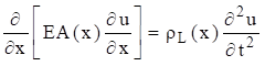
The term  is the product of the elastic modulus and cross-sectional area. The equation for a uniform rod is

Note that

Equation (1.2) is a common formula for one-dimensional wave propagation. Similar equations govern the propagation of sound in a pipe and the torsional vibration in a shaft. Note that a wave is the phenomenon in which physical energy propagates through space relative to a medium. Wave propagation is discussed throughout this document, as shown for seismic waves in Section 18.6.1 as for example.
The method of separation of variables can be applied to equation (1.2) as


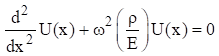
Substitute equations (1.4) and (1.6) into (1.2). The resulting spatial equation after some simplification is
Longitudinal waves are non-dispersive. The group and phase wave speeds are equal. The wave speed is calculated from the elastic modulus and mass density.

The speed of sound is related to the frequency and wavelength by

The spatial equation can be expressed as

The spatial solution is

The  values in equation (1.4) are coefficients that depend on the boundary conditions.
The boundary condition for a fixed left end is

The boundary condition for a free left end is

The same boundary conditions could be applied at the right end. The longitudinal natural frequencies are given in the following table.
| Configuration | Natural Frequencies | Mode Shapes |
|---|---|---|
| Fixed-Free |  |
 |
| Free-Free |  |
 |
| Fixed-Fixed |  |
 |
The mode shapes are normalized to a value of one. Note that the Free-Free beam also has a rigid-body mode at zero frequency. Further solution details are given in Reference [4]. Also, longitudinal vibration is revisited in Section 19.2.
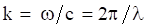
The previous method of separation of variables is a modal solution approach. As an alternative, a wave solution can be applied to equation (1.2) as

The wavenumber  is related to the angular frequency, longitudinal wave speed and wavelength as
Rod Longitudinal Vibration Energy Formulas
Natural frequency and modes shapes can also be derived from a rod’s energy terms via the Rayleigh-Ritz or finite element method. The following formulas are given for reference.
The total strain or potential energy  of a uniform rod is

The total kinetric energy  of a uniform rod is


The suspended beam can be idealized as a free-free beam for longitudinal vibration. The pendulum hammer is raised to some initial angular displacement and then released. The hammer strikes the beam’s end plate on the left end, delivering a force impulse. The longitudinal modes of the beam amplify the input energy and deliver a base input shock pulse to the test article mounted near the right end.
Bai and Thatcher described this shock test method in Reference [5]. This method is still used today, although the pendulum hammer is often replaced by a pneumatic gun firing a projectile into the beam’s end plate.
The goal was to choose the beam length so that its fundamental frequency would match the “knee frequency” of a shock response spectrum specification at 2000 Hz. (Further information on this type of specification is given in Section 18. The length for an aluminum beam to meet this goal is calculated as

Note that the longitudinal wave speed in aluminum is about 200,000 in/sec.

(https://www.enginelabs.com/engine-tech/cam-valvetrain/when-do-i-know-my-valvetrain-is-in-distress/)
Spring surge is another form of longitudinal vibration, which arises because springs have both stiffness and inertia properties. This is in contrast to the usual simplifying assumption in vibration analysis that springs are massless. Springs used in high-speed machinery must have natural frequencies well in excessive of the frequency of motion that they control. Otherwise, the spring itself may resonate, resulting in loss of engine performance or even catastrophic failure. This can occur in automotive value springs when the engine camshaft RPM speed is increased well above the normal operating speed. Race car engines are at particular risk for this problem. Spring surge is also a potential concern when coil springs are used as isolation mounts for equipment.
The following spring natural frequencies are taken from Reference [6]. Note the similarities with the longitudinal rod formulas in Table 1.1.
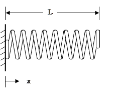
The fundamental frequency of the fixed-free spring is

Its corresponding normalized mode shape is

The wave speed in the spring is

The wave speed equation applies for other spring boundary conditions as well.

The fundamental frequency of the fixed-fixed spring is

The corresponding normalized mode shape is

Note that the Fixed-Fixed and Free-Free cases have the same natural frequency equation.

The simplified fundamental frequency formula for a spring with and end mass  is
is
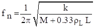
A more rigorous formula is

The corresponding mode shape is


Consider a thin ring with a rectangular cross section and with completely free boundary conditions. The ring frequency corresponds to the mode in which all points move radially outward together and then radially inward together. This is the first extension mode. It is analogous to a longitudinal mode in a rod. The ring frequency is the frequency at which the longitudinal wavelength in the skin material is equal to the vehicle circumference.

The ring frequency is an important concept for launch vehicles. The front end of a launch vehicle is typically composed of cylindrical shell segments which house avionics components and the payload. These shells tend to have notable vibration responses at their respective ring frequencies due to external acoustic environments and stage separation shock events. Furthermore, there is a rule-of-thumb in statistical energy analysis (SEA) that a cylinder tends to behave as a flat plate above its ring frequencies. This is a simplifying assumption. Also note that the ring frequency is an idealized concept for a cylindrical shell. In practice, cylindrical shells tend to have a high modal density near the ring frequency.
Consider an aluminum launch vehicle cylindrical shell with a diameter of 72 inches. Again, the longitudinal wave speed in aluminum is approximately 200,000 in/sec. The ring frequency is

